What is SOFIA?
The Stratospheric Observatory for Infrared Astronomy (SOFIA) is an extensively modified Boeing 747SP aircraft carrying a 2.7-meter (106 inch) reflecting telescope (with an effective diameter of 2.5 meters or 100 inches). Especially interesting objects for SOFIA's observations are galaxies, star forming regions, the interstellar medium, our solar system, planets and comets.
SOFIA is a joint project of the German Aerospace Center (DLR) and the National Aeronautics and Space Administration (NASA). The Deutsches SOFIA Institut (DSI) at the University of Stuttgart coordinates the scientific operations on the German side. The American scientific operations are planned by the NASA Ames Research Center (ARC) and the Universities Space Research Association (USRA). Flight tests and flight operations are led by the NASA Armstrong Flight Research Center (AFRC) to the north of Los Angeles. The NASA Ames Research Center (ARC) to the south of San Francisco conducts the scientific research flights. To facilitate smooth telescope operations, the majority of DSI employees are continuously posted on site in California.
|
Beginning of development phase: |
January 1997 |
|
Beginning of modifications in Waco, Texas: |
January 1999 |
|
End of modifications and telescope integration: |
February 2006 |
|
Ground vibration test conducted successfully: |
June 2006 |
|
Engine tests up to the performance limit: |
August 2006 |
|
New paint finish: |
September 2006 |
|
First test flight after modification: |
April 2007 |
|
First test flight with open observation hatch: |
December 18th 2009 |
|
Planned operational life: |
20 years |
|
Number of observation flights per year: |
ca. 160 |
|
Telescope platform: |
Boeing 747SP airplane |
|
Altitude for astronomical observations: |
12000-14000 m |
|
Observation time at 39.000 ft or higher: |
> 6 hours |
|
Total observation time per year: |
> 960 hours |
|
Surrounding temperature in the telescope cavity: |
210-330 K |
|
Operating team: |
3 people in the cockpit |
|
Home base: |
|
|
Scientific base |
|
The platform for SOFIA is a 747 SP airplane. "SP" stands for special performance and denotes a shorter version of the jumbo jet. The telescope is located in the rear of the fuselage, which has a sealable opening. The passenger cabin and the telescope cavity are separated by a pressure bulkhead. During observations, the instruments and the scientists are in the passenger cabin and the telescope - when the hatch is open - is exposed to the conditions that exist outside the airplane. At an altitude of 13 km, this means temperatures around -60 degrees Celsius and about a fifth of the air pressure that exists on the ground. To increase the speed at which the telescope adapts to these conditions, it is cooled down starting even before takeoff. During takeoff and landing, the cabin is protected from dust, dirt and strong air vortexes by a sliding door. The door is also meant to prevent the telescope's mirror planes from fogging up and freezing as the plane climbs higher. The cabin door is only opened once the plane has reached observation altitude.
Building Process
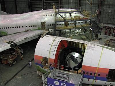
In order to be used as a flying observatory, the Boeing 747 had to be thoroughly renovated and modified. The machine was completely redesigned to make room for the telescope cavity and the workspaces for the scientists. The most difficult parts of this process were the construction of the opening in the fuselage, the design of the telescope cavity and the integration of the telescope with its bearing. In 1999, the SOFIA airplane was transferred to Waco, Texas for the alterations and the integration of the telescope by L3-Communications Integrated Systems. To enable the engineers to check their plans with a 1:1 model of the airplane before the actual alterations began, a structurally identical segment of a scrapped Boeing 747 SP was brought to Waco.
You can find the pictures of the transport of “Section 46” in our gallery. The team practiced the most important alterations on this segment: opening the airplane fuselage and integrating the pressure bulkhead and a model of the telescope. The experiences that the team had during this dry run were immensely helpful when they modified SOFIA.
For information about how the real telescope was integrated into the airplane, please see the section about the telescope on this page.
Pictures of the modification work in 1999
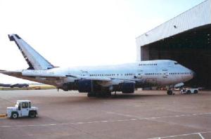
SOFIA was transferred to Waco, Texas ..
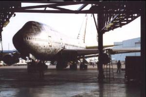
.. and towed into the hangar..
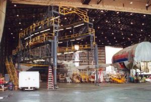
.. where a dry dock waited for the airplane (in the background you can see “Section 46”)
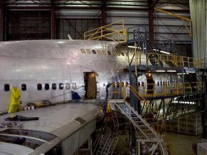
Extensive work was done on all parts of the machine.
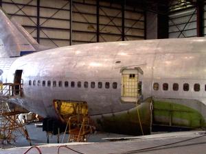
Special attention was paid to the rear part of the plane, where the telescope was later integrated.
--
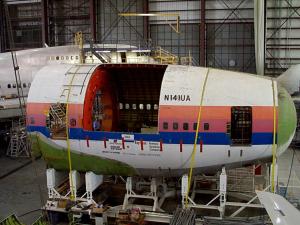
In the meantime, the opening for the telescope cavity was made and the pressure bulkhead was built in (the red area in the telescope opening).
Here you can see the pressure bulkhead (The telescope was later hung in the opening):
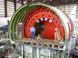
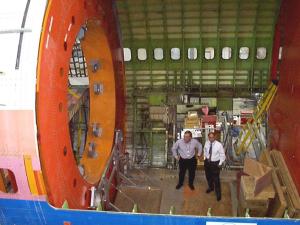
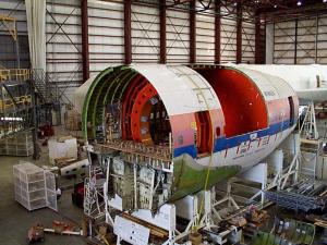
--
At the end of 1999, a model of the telescope was built into Section 46:
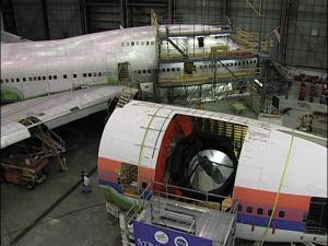
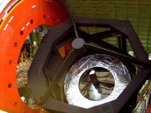
Below, you can see the telescope model. The original telescope was built in Germany and was integrated into the airplane in the United States.
After the transfer of the Telescope from Germany to the USA
September 2002:
After the construction of the telescope was completed in Germany, it was transferred to Waco, Texas. Under the leadership of L3-Communications Integrated Systems, it was integrated into the airplane in close cooperation between DSI and DLR. It was divided into three parts for transport: The telescope frame, the suspension and the primary mirror.
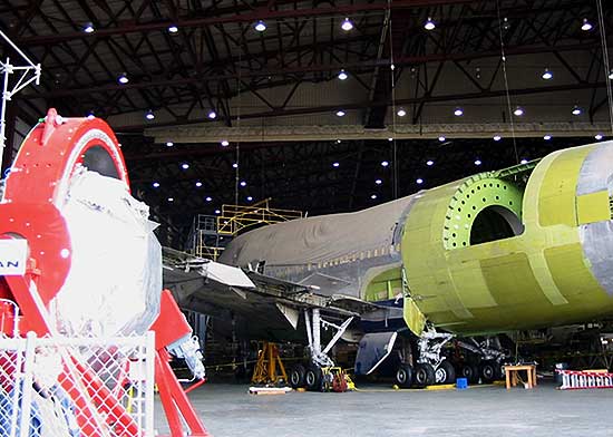
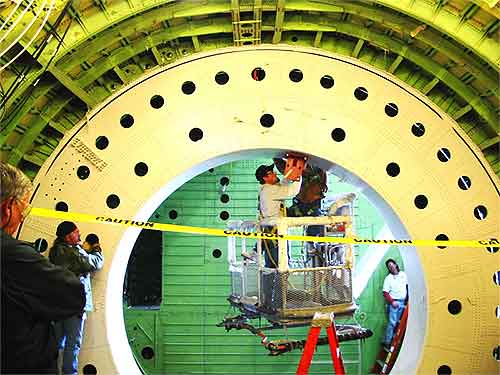
The Boeing 747 SP was modified by the American engineers when they cut an opening for the telescope into the fuselage and separated it from the actual cabin with a pressure bulkhead. In the image below, the bulkhead is the large green/yellow ring with holes that are used to mount the telescope suspension.
1. Installation of the Suspension
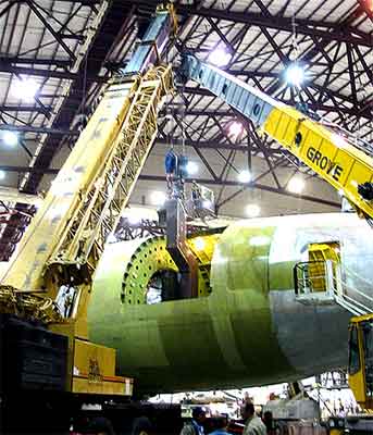
The telescope suspension was carried to the airplane by a crane that was especially modified for this task. A second crane was needed to help with the actual installation:
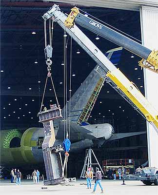
Fixation points were installed on the bulkhead to stabilize the telescope suspension.
The next part was the most difficult. In order to insert the telescope suspension into the fuselage, two cranes had to stabilize the 9300 kg load.
Once the telescope bearing was inside the plane, it had to be screwed on very tightly.
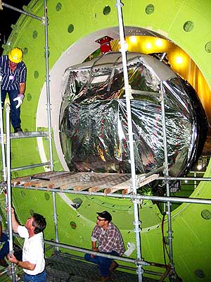
January 2003
We did it!
Tom Bonner – SOFIA Project Manager – examined the finished work with relief.
Before the heavy telescope frame could be built in, the airplane had to be placed on its own landing gear (downjacking) to distribute the extra weight evenly.
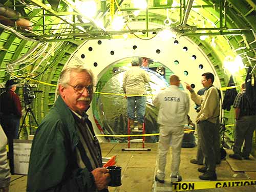
May 2003
2. Installation of the Telescope Frame
The telescope frame, known as the metering structure, had to be mounted on the telescope suspension in the open part of the cabin. It had to be fixed exactly onto the starframe, below, which serves as a connecting piece between the frame and the Nasmyth tube.
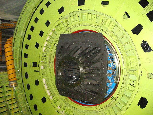
In order for the 750 kg telescope frame to be installed as described, it had to be lowered into the opening very carefully by a crane.
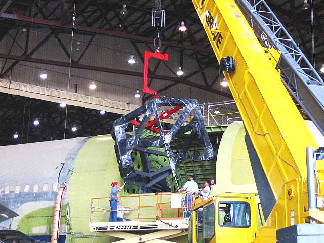
Once the metering structure was inside of the airplane, it was attached to the starframe so that it could be supported by the Nasmyth tube and the telescope suspension.
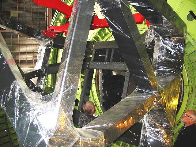
July 2003
3. Installation of the Primary Mirror
As the largest of the three mirrors, the primary mirror was placed into the telescope frame. Next, it was rolled to the airplane in a special wagon (seen from the side, below).
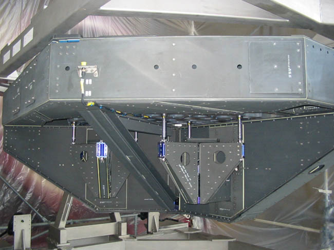
After the mirror arrived at the airplane, it was attached to the crane.
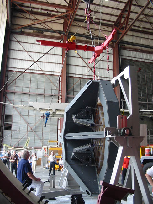
The crane lifted the 1680 kg primary mirror with its 2,7 m diameter to the fuselage.
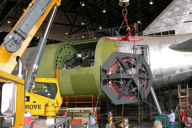
The mirror was now inside the airplane, but it still had to be attached to the frame.
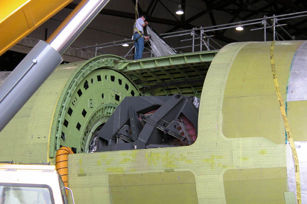
The mirror was then mounted and installed. However, it was still covered by a protective red tarp because if its extreme sensitivity to external conditions.
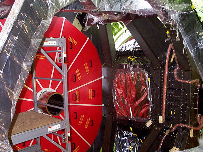
From this perspective, you can see the entire telescope structure with the primary mirror (red) and the wide-angle camera with its aluminum cover on the 8 o’clock position of the telescope ring.
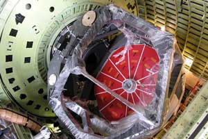
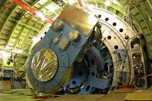
The telescope structure protrudes into the cabin. You can clearly see the opening of the Nasmyth tube (with a protective cover) and the flange for the fixation of the scientific instruments.
The telescope bearing is filled with 30 µm of oil, which allows the telescope to move with nearly zero friction.
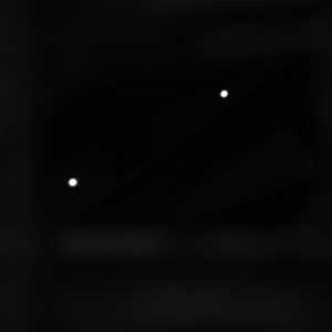
December 2003
In the image, below, you can see two lasers that were captured with the wide-angle camera on the support structure. This was the first test of the tracking system and camera orientation.
|
Beginning of development phase: |
September 1997 |
|
Transfer to Waco, Texas, where the installation of the telescope in the airplane took place: |
September 2002 |
|
Weight of the telescope including scientific instruments: |
ca. 20.000 kg |
|
Configuration: |
Cassegrain telescope with a Nasmyth focus; permanent access to the scientific instruments from the cabin during the mission |
|
Structure: |
CFRP-structure in the shape of a dumbbell; reflector lens barrel in a lattice grid structure |
|
Rotation and isolation system: |
Hydrostatic bearing with two ring segments, 1.200 mm diameter, 10-30 bar supply pressure |
|
Drive system for rotation: |
High speed drive for elevation and fine drive (brushless curved direct current linear motor) for elevation, cross-elevation, and line-of-sight (L.O.S.) |
|
Vibration isolation system: |
For every 12 air spring/damper elements in longitudinal and tangential direction around the hydrostatic bearing |
|
Primary Mirror (PM): |
Diameter 2.70 m, effective opening 2.50 m, lightweight ZERODUR structure on 18-point whiffle-tree support, PM f-number f/1.28, aluminum quenched and tempered |
|
Secondary Mirror (SM): |
SiC material, 352 mm diameter, aluminum quenched and tempered |
|
SM Functions: |
Focusing, alignment, chopping (2-axis in any direction, offset, 3-punkt, stationary) |
|
Tertiary Mirror: |
2 level mirror, partially transmissive (gold quenched and tempered) and reflective (aluminum quenched and tempered |
|
F-Number for complete system: |
f/19.6 |
|
Spectral range: |
0.3 to 1,600 mikrometers |
|
Unvignetted visual field: |
8 arcmin |
|
Range of motion: |
Elevation 15-70 degrees (20-60 degrees unvignetted), cross-elevation and L.O.S. ° 3.0 degrees |
|
Image quality: |
80% energy in 1.5 arcsec diameter circle at 0.6 micron wavelength |
|
Image stability: |
0.2 arcsec rms for On-Axis Focal Plane Tracking |
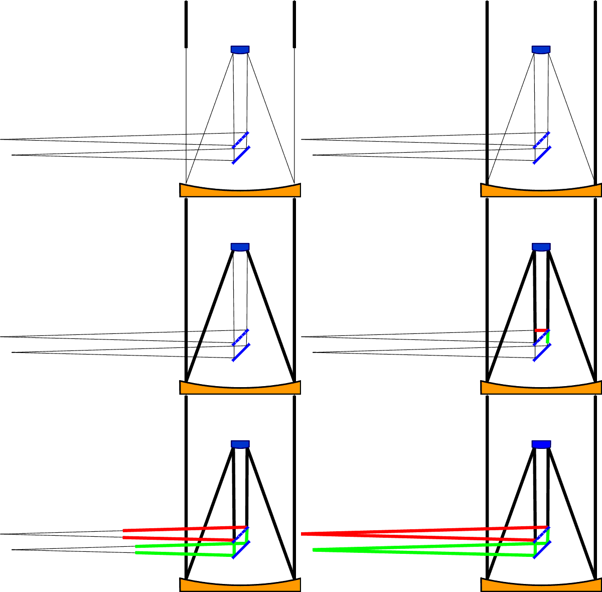
The telescope consists of a primary mirror with a 2.7 m diameter, a small secondary mirror (diameter: 34 cm) and a tertiary mirror. The primary and secondary mirror have a focusing effect and the tertiary mirror deflects the rays by 90°. The focus of the rays is therefore lateral to the axis (Cassegrain focus in Nasmyth arrangement). The tertiary mirror is actually composed of two parts. The first mirror is semipermeable: infrared rays are reflected, but visible rays pass through unhindered and hit the second mirror. This created two foci: one for the infrared rays and one for visible rays.
The SOFIA telescope was developed and built by the companies MT Aerospace AG und Kayser-Threde GmbH on behalf of DLR. Dozens of other companies in Europe worked on the development of the telescope as subcontractors of the main two companies.
The most important milestones during the building process are shown here in chronological order.
September 1997: SOFIA’s Primary Mirror is Delivered for Further Processing
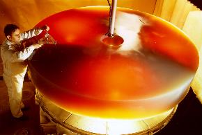
The primary mirror has a diameter of 2.7 m. It consists of “Zerodur” glass ceramic from SCHOTT. This material is similar to the “Ceran” glass ceramic cooktops in modern kitchens. These cooktops are extremely resistant to changes in temperature. The unfinished mirror, which weighed about 4 tons, already had a spherical surface and a hole in the center for the tertiary mirror mount.
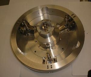
February 1999: The Prototype of the Secondary Mirror Drive is Completed
The secondary mirror can execute different movements. The most important function is the “chopping”. During chopping, the secondary mirror is lightly tilted back and forth so that the telescope can observe two different points on the sky that are nonetheless very close to each other. With the movable secondary mirror, the focus can be set and fluctuations in low frequency waves can be corrected.
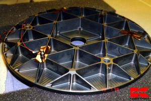
July 1999: The Secondary Mirror is Completed
The secondary mirror has a diameter of 34 cm and is composed of silicon carbide (SiC). Like the primary mirror, it also has a lightweight structure. The secondary mirror hangs from a three-point support about 1.8 m above the primary mirror.
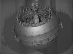
The Production of the Bearing Ball
The bearing ball was the first part of the load-bearing structure to be completed. It was manufactured using a casting process. Later, it was slid over the Nasmyth tube. A thin oil film between the bearing ball and the bearing ring in the pressure bulkhead allow for the telescope’s nearly frictionless movement. After a nickel coating, the surface was worked on mechanically so that the spherical shape and the surface would be perfect.
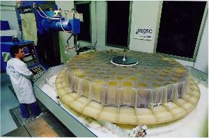
The Primary Mirror’s Weight is Reduced
120 blind holes were milled in back of the mirror. At this point, the mass was only 900 kg. The back of the mirror now had a honeycomb structure. Some of the bars were only 7 mm thick. This process took 18 months. Further steps to be taken until the summer of 2000 were the fine tuning and polishing of the optical surface.
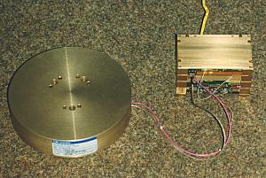
September 1999: Gyroscope
Below is the prototype of the gyroscope with which SOFIA is stabilized. Inside of this cylinder, there is a 3 km long fiber optic cable. For every direction, there is one roundabout that is attached to the telescope structure and that helps align the telescope’s tracking system. From time to time, the position of the roundabouts is compared to the cameras’ observations and corrected, if necessary.
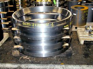
June 2000: Bearing Rings
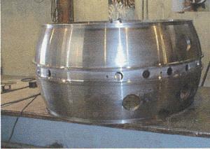
The complement to the bearing ball (see below) are two rings that encompass the ball. A thin oil film allows for the nearly frictionless movement of the bearing ball by +/- 3° in all directions against the rings (hydrostatic bearing). The rings were forged and then altered. Their diameter is about 1.6 m and one ring weighs about 200 kg.
July 2000: Telescope Suspension
Another heavy part (600 kg) was finished. The “inner cradle” is a part of the internal suspension. The movement of the bearing ball against the bearing rings is limited to +/- 3°. To reach a larger movement of 90° vertically, another bearing must be built on top of this component.
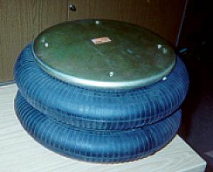
Anti-Vibration Insulators
To keep the engine vibrations from reaching the telescope, a kind of shock absorber system was constructed. Twelve of these anti-vibration insulators were placed in a circle between the axis of rotation and the pressure bulkhead. They are similar to car tires, but the pressure must be checked constantly during the flight. When the telescope changes direction as compared to the wall of the airplane, the pressure increases.
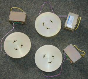
August 2000: Fiberglass Gyroscope
The three fiberglass gyroscopes for the stabilization of the telescope were completed. On the telescope structure were completed. They were attached to the telescope structure in the open cabin between the Nasmyth tube and the rotary flange. The telescope can remain focused on one point in the sky with an accuracy of 0.2 arcsec. This is like focusing on a penny from a distance of 16 km.
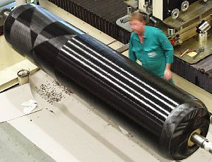
September 2000: Nasmyth Tube
The Nasymth tube that is stored in the bulkhead was nearly completed at this time. It was made of Carbon Fiber Reinforced Polymer Composites (CFPR) with a wall thickness of only 30 mm. The fibers were wrapped around a mold in different directions to reach high rigidity and load-bearing capacity. An approximately 1m piece of the tube shown here was later severed for the regulation of mechanical values.
October 2000: The Primary Mirror is Polished
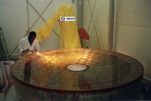
The mechanical work on the primary mirror was coming to a close. After the weight of the mirror was reduced and the mounting brackets were attached, the surface of the primary mirror was smoothed into a paraboloid. The mirror would still be polished for a while. Before the telescope could be used for scientific observations, the surface still had to be coated with aluminum.
December 2000: More about the Telescope Suspension
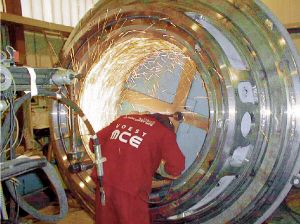
The suspension of the SOFIA telescope is a significant matter. On behalf of MAN Technologie, the company Voest MCE in Austria welded the telescope’s main load-bearing structure together (See July 2000). The structure shown below weighs 1.9 tons and has a diameter of 2.5 m. The sparks resulted from the grinding of the welding seams.
March 2001: Assembly and Measurement of the Bearing Rings
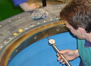
Both bearing rings are in the “inner cradle” and were being measured in the image below. The rings are highly precise: the diameter specification of 1.2 m was met with an accuracy margin of 16/1000 mm. Between the rings and the bearing balls that hold the Nasmyth tube, there is a gap with an approximately 30 µm thick oil film. This allows for the telescope’s subtle movement of up to 3° in all directions.
January 2002: The Support Structure of the Primary Mirror
The primary mirror’s support structure, which is made of carbon-reinforced plastic, was completed. It was built into the open telescope cavity.
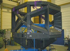
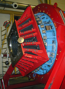
Starframe
In the image below, the starframe can be seen. It connects the Nasmyth tube to the support structure (see above image).
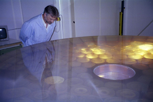
May 2002: The Primary Mirror is Completed
After the primary mirror was sanded and polished, DLR employee Dr. Lilienthal took a look at it (below). It had a nearly perfect optical surface. It is easy to identify the comb-like structure on the back of the mirror, which helps provide some weight relief for the mirror.
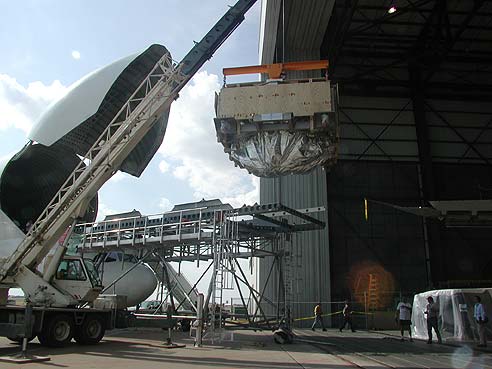
September 2002: The SOFIA Telescope arrives in the USA
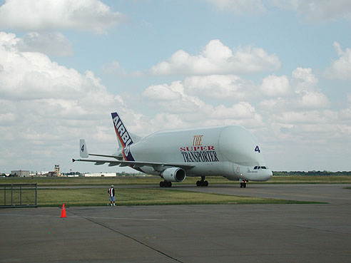
The telescope, which was built in Germany, was flown to the USA on an Airbus Beluga wide-body aircraft so that it could be integrated into the Boeing 747 SP by American and German engineers and technicians. The image below shows how the mirror looked as it was offloaded from the transport airplane at the Texan Airport in Waco after a 7000-mile journey.
See the text about the airplane (above on this page) to find out how the telescope was built into the airplane.
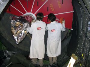
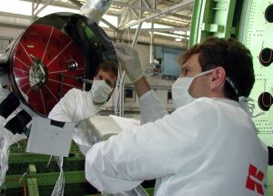
Two engineers from the company Kayser-Threde removed the primary mirror’s protective cover in the airplane to prepare the telescope for its first star observation:
The secondary mirror is mounted and optically adjusted in the airplane by Kayser-Threde employees:
The SOFIA telescope has no permanently installed detectors. Therefore, it can be used with different instruments based on the task at hand. The instrument is attached to the telescope’s flange, which is located in the passenger cabin of the airplane.
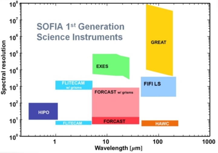
For SOFIA’s first observation cycle, nine new instruments were developed. They used different measurement techniques to be able to meet various astronomical observation goals. The instruments can be divided into three categories:
|
1. |
Instruments that belong to the SOFIA observatory’s standard equipment. These instruments are characterized by their sophisticated technology and are robust. This ensures that astronomers can conduct modern observations. The instruments are operated and maintained by American SOFIA employees, who also assist external scientists with their observations. The IGAs include: |
|
|
|
|
|
|
|
High-resolution Airborne Wideband Camera |
|
|
|
Faint Object InfraRed CAmera for the SOFIA Telescope |
|
|
|
First Light Infrared Test Experiment CAMera |
|
|
2. |
Instruments that were developed by a “Principal Investigator” Team (IPI), which now develops and maintains them. These instruments are in a constant process of development and refinement and can only be used in cooperation with the PI Instrument Team. Both German instruments are in this category: |
|
|
|
|
|
|
|
Field Imaging Far-Infrared Line Spectrometer |
|
|
|
German Receiver for Astronomy at Terahetz Frequencies |
|
|
|
|
|
|
|
On the American side in the IPI category: |
|
|
|
|
|
|
|
Echelon-Cross -Echelle Spectrograph |
|
|
3. |
Instruments that were developed for special tasks and observations (ISA). These instruments are based on new and partly untested technology and are intended for very special astronomical programs. |
|
|
|
High-speed Imaging Photometer for Occultation |
|
An important characteristic of the instruments is their resolution, or their ability to separate the rays of adjacent wavelengths. In the overview, above, the individual first generation SOFIA instruments are shown with their resolution in their wavelength range.
1σ line flow in 1 hour corresponds to ~3 x 10-18 Wm-2 with R = 103 and with 10 μm
Which Instruments are Flying with SOFIA Now?
- SOFIA Instrument Suite
The USRA Website lists the instruments that are currently flying with SOFIA.


